Hall sensor actuation
We will gladly help you to choose the right magnet.
Decision criteria for choosing the right magnet:
- switch type
- desired switching characteristic
- switching distance
- way of movement
- dimensions, tolerances, weight
- temperature range
- surrounding materials
- mounting options
- existing space, etc.
Principle of operation
The position sensors are Hall effect sensors. With the help of a permanent magnet, depending on the magnetic flux density, a switching or analog output signal can be generated. Due to the compact design, positions, speeds, states, etc. ... can be detected and evaluated without contact.
The magnetically actuated semiconductor sensors can basically be divided into three different versions:
- Digital
- Analog
- With built-in magnet
To actuate the sensors, we offer several rod and ring magnets.
Bar magnets of various sizes and strength are particularly suitable for sensors with unipolar switching characteristics.
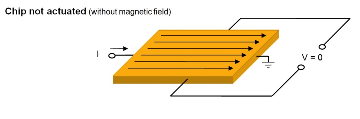
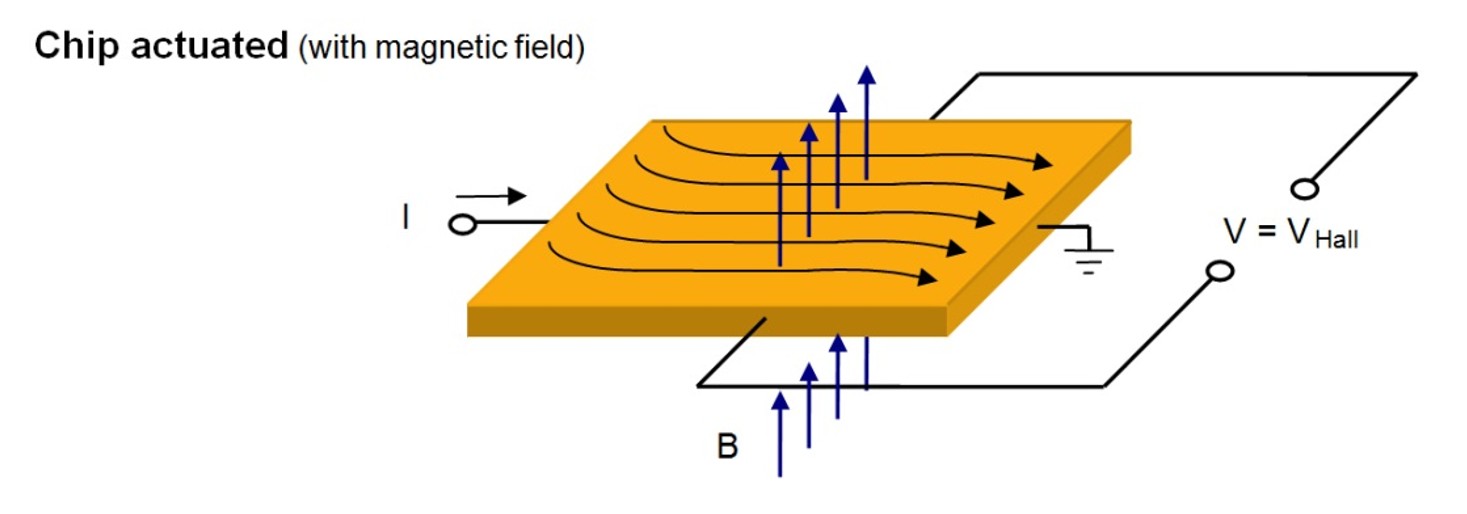
Ring magnets with alternating north and south poles on the circumference are particularly suitable for sensors with bipolar switching behavior. In Hall effect sensors, the semiconductor chip is supplied with a current I and allows a magnetic field (B) to act perpendicular thereto. This creates a voltage in the chip at right angles to the field and the current. These sensors work pole-dependent.
As mentioned above, there are various criteria to take into consideration for choosing the right magnet. There are many variations are possible.
Performance comparison
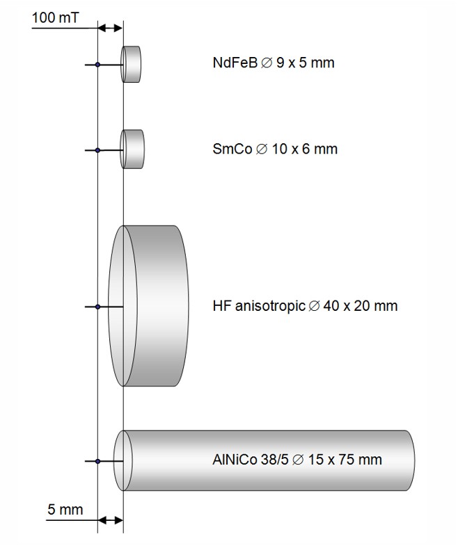
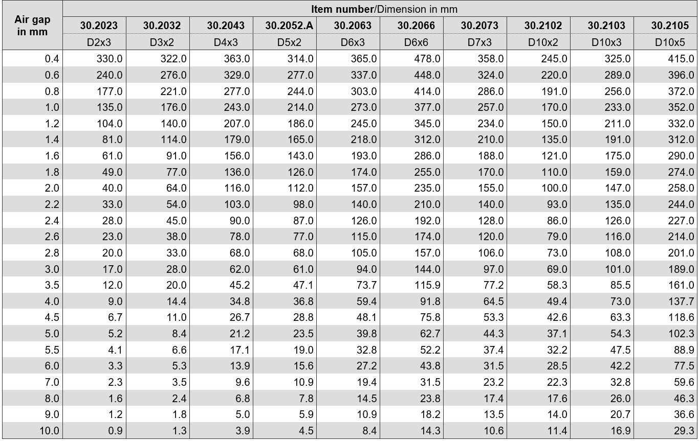
The magnets are designed to produce a field of 100 mT at a distance of 5 mm from the pole face.
See also the following tables with the data of the flux density of neodymium magnets depending on the air gap.
Flux density in mT versus air gap for NdFeB disc magnets
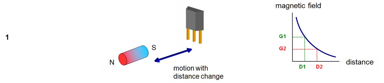
Digital sensors
If the magnet is guided to the sensor during the frontal approach, it will only switch on at the distance D1. The magnet strength G1 is needed. If he moves away again, he switches off only at the distance D2. So a lower magnet strength is needed to "hold" the sensor.
Unipolar or bipolar magnets can be used.
Some application examples:
Frontal approach unipolar
Lateral shift unipolar

Lateral shift bipolar
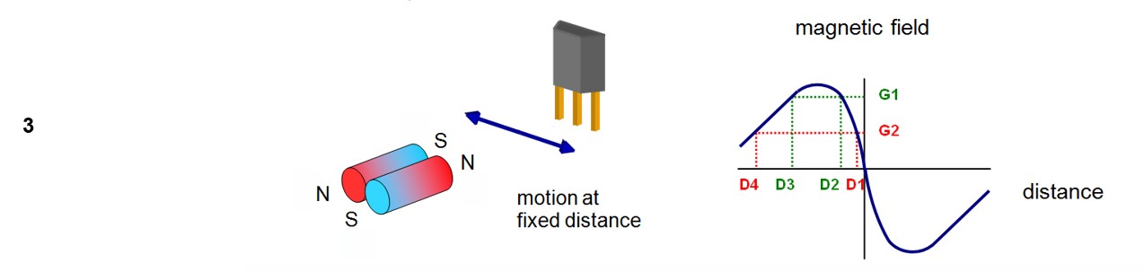
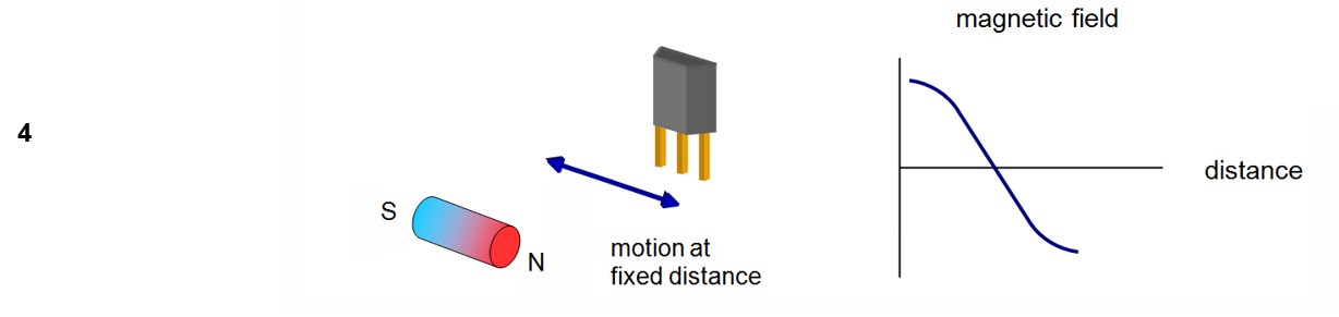
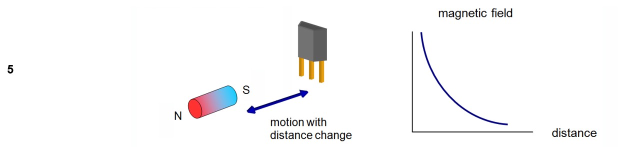
Analog sensors (distance measurement)
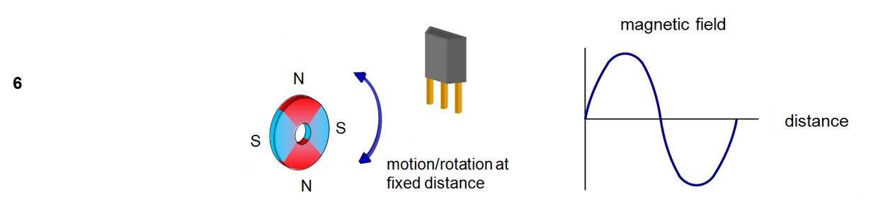
The first illustrated arrangement is the lateral approach. Between magnet and sensor a close, fixed distance is maintained. If the bar magnet is moved back and forth at a fixed distance, the sensor experiences a negative magnetic field when approaching the north pole and a positive one when the south pole is approaching. This approach is easy to set up and allows, with the use of a correspondingly long magnet, the position detection over long distances. The output characteristic curve of this distance measurement arrangement is the most linear of all the arrangements shown, especially if a pole piece is attached to both magnet ends. However, the favorable characteristic curve requires strict adherence to the air gap between the sensor and the magnet.
Some application examples:
Lateral shift bipolar
Frontal approach unipolar
Frontal change bipolar
Reed switch actuation
 We will gladly help you to choose the right magnet.
Decision criteria for choosing the right magnet:
- switch type
- desired switching characteristic
- switching distance
- way of movement
- dimensions, tolerances, weight
- temperature range
- surrounding materials
- mounting options
- existing space, etc.
Technical information
Reed switches can be used wherever switching operations are to be carried out without contact.
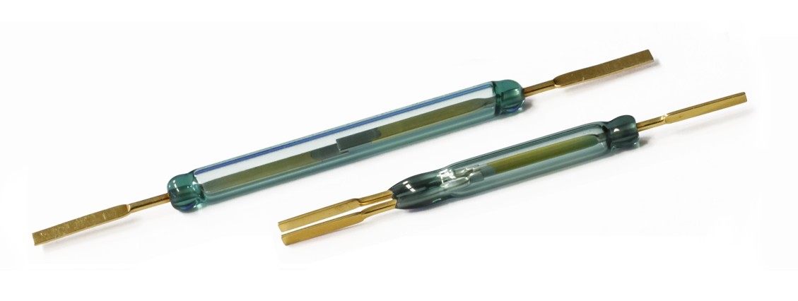
Basic element of the Reed switch, which is always magnetically actuated, is a pair of contact tips (reeds) made of ferromagnetic material. The contact tips are welded into an inert gas-filled glass tube.
When a magnet approaches the Reed switch and one of the contact tips is flooded with the N-pole and the other with the S-pole, the contact tips close. The contact tips open again when the magnet is removed or rotated so that both contact tips are flooded with the same pole (N or S).
Reed switch open

Reed switch closed

Another type of Reed switch (change-over switch) has 3 contact tips so that not only switching on and off is possible but also a change over.
Change over switch

Selection of the most important functional characteristics
The drawings show how the different types of magnetization act on the Reed switches.
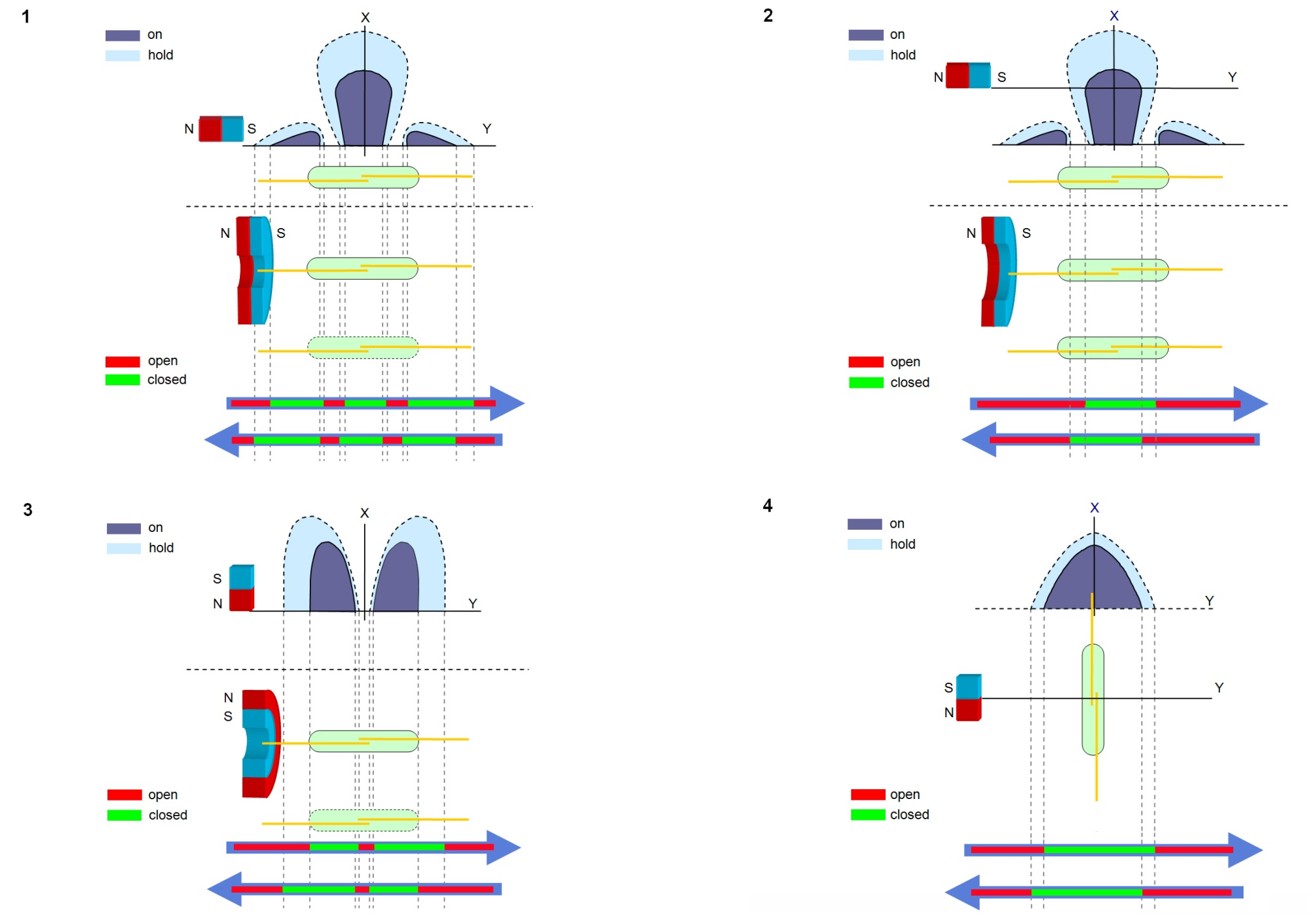
Selection of the most important Reed switch operations
Approach movement
In all systems listed here, the Reed switch and magnet must be close enough to each other. The sensitivity of the switch and the field strength of the magnet determine the distance between the switch and the magnet. Corresponding approach or removals of the magnet determine the closing or opening of the contact tips. The distance of the magnet to the switch is always lower for closing the contacts than that at which the contacts open again.
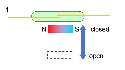 |
A magnet moved perpendicular to the Reed switch. The switch closes only once, at maximum magnet displacement. |
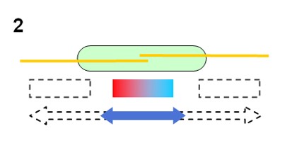 |
A magnet moved parallel to the Reed switch. The switch closes up to three times at maximum magnet displacement and once at minimum displacement. |
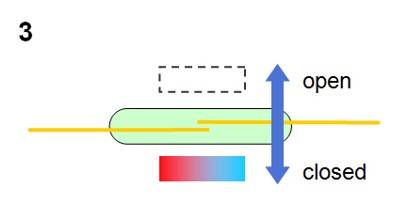 |
A magnet operated horizontally to the switch longitudinal axis. The magnet moves this time at right angles to the switch longitudinal axis. The switch closes only once. |
 |
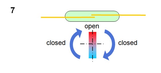
A magnet in swiveling motion to the reed switch. The magnet must be moved at a large angle so that the switch closes once. |
 |
A ring magnet in parallel movement to the Reed switch can have up to three closing points at maximum displacement or one closing point with minimum displacement. |
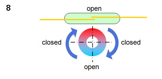
Rotation
Following are some typical applications where different magnets are in rotation:
 |
 |
 |
 |
Shielding
With the stationary arrangement of a Reed switch and magnet, the contact tips are closed. If the magnetic field is diverted through a shield made of ferromagnetic material, which is pushed between the magnet and the switch, the contact tips open again. By completely removing the shield, the contact tips are again magnetically actuated and close.

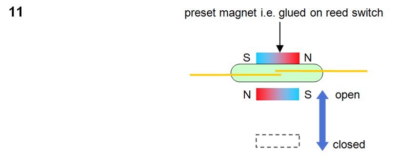
Magnetic preload
This effect is achieved by bringing a magnet close to the switch, keeping it closed (normally closed contact). If a second magnet with reversed polarity or a coil with a stronger field is moved to the switch, the switch opens again, as the magnetic lines of force cancel each other.